Omron G3na 210b Wiring Diagram
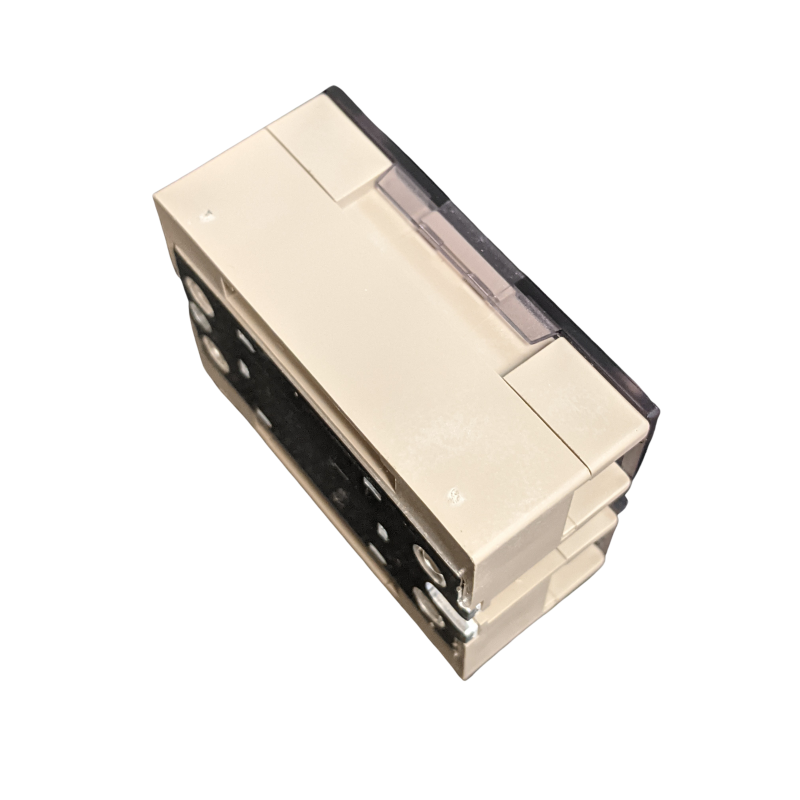
All models feature the same compact dimensions to provide a uniform mounting pitch. To remove the relay from the din track, pull do wn on the tab with a screwdriver in the direction of the arrow.
Omron G3na 210b Wiring Diagram theintoxication
All models feature the same compact dimensions to provide a uniform mounting pitch.

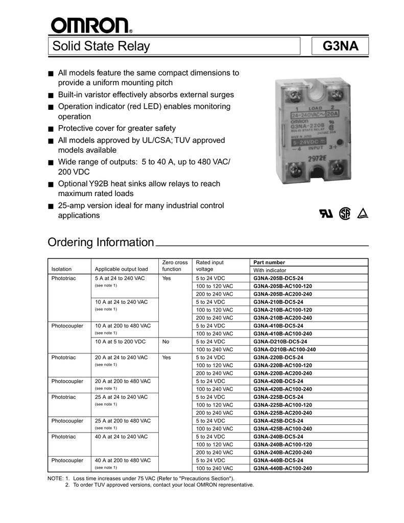
Omron g3na 210b wiring diagram. The operation indicator enables monitoring operation. • all models feature the same compact dimensions to provide a uniform mounting pitch. Model rated voltage operating voltage impedance (see note 1.) input current voltage level.
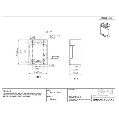
Get a quote product support. Rated input voltage range from 5vdc to 24vdc. 5.6 47.6 5 30 4.5 35±0.2 90±0.4.
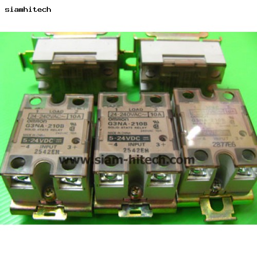
Available in a wide range of currents. (at 500 vdc) dielectric strength. Operation indicator (red led) protective cover for greater safety.
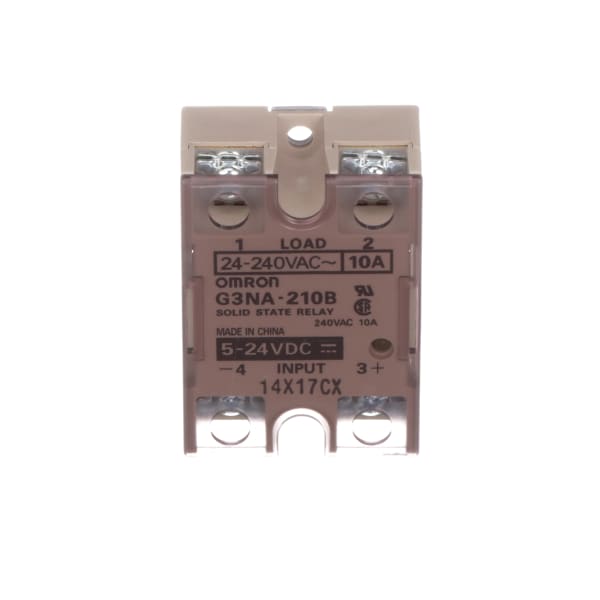
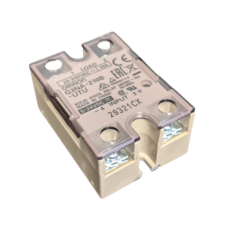
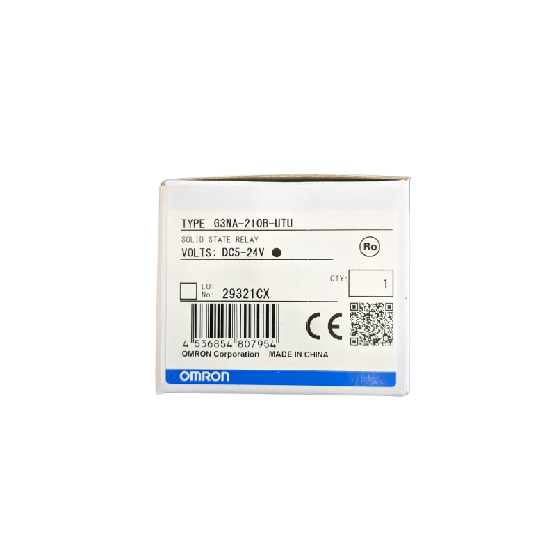
2,500 vac, 50/60 hz for 1 min. Output w/heat sink 10a, input voltage 5 to 24vdc, voltage output 24 to 240vac, turns on at zero cross, 3 phase, switch type phototriac When an omron heat sink (refer to options) or a heat sink of the specified size is used.
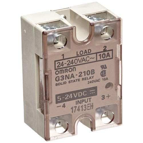
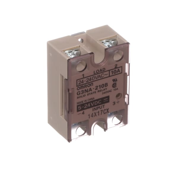
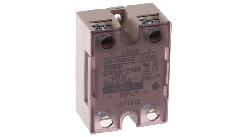
Model rated voltage operating voltage impedance (see note 1.) voltage level must operate voltage must release voltage. It has a load rating of 24 to 240vac at 10 amp, with an input of 5 to 24vdc. Please call or email us with your request.
The operation indicator enables monitoring operation. 27 mm supply voltage ac: It is certified by ul and csa standards.
Technology satisfying customer needs with. False rated operational voltage, ac: When an omron heat sink (refer to options (order separately)) or a heat sink of the specified size is used.
The orientation indicated by the external dimensions is not the correct mounting orientation. Rated output load is 10a at 24vac to 240vac. All models feature the same compact dimensions to provide a uniform mounting pitch.
On/off control number of phases: Wiring power supply voltage make sure that the power supply to the sensor is within the rated voltage range and do not apply 100 vac or more if the sensor is a dc model, or otherwise the sensor may explode or burn. Introducing omron's unique efc sockets and probe pins for ic testing.
The operation indicator enables monitoring operation.
Omron G3na 210b Wiring Diagram theintoxication

Omron Automation G3NA210BDC524 Solid State Relays; Genral Purpose; Out10A; Out 24240VAC
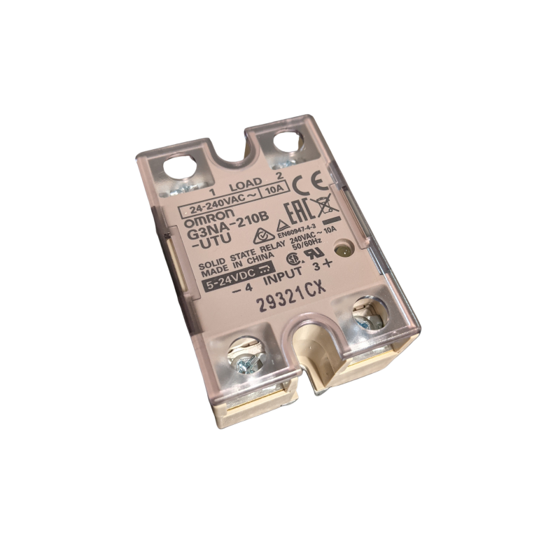
Omron Solid State Relay G3NA210BUTU SSR
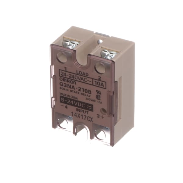
Omron Automation G3NA210BDC524 Solid State Relays; Genral Purpose; Out10A; Out 24240VAC

OMRON G3PA210BVD DC524 10A 24240VAC SSR 524VDCcontrol
Omron Solid State Relay G3NA210BUTU SSR
Theatrical cue lights part 4 Stompville

Omron G3NA210BDC524 Solid State Relay, Zero Cross Function, Yellow Indicator, Phototriac
Omron Automation G3NA210BDC524 Solid State Relays; Genral Purpose; Out10A; Out 24240VAC

Omron Automation G3NA210BUTU DC524 Solid State Relay, 524 VDC, SPSTNO, 10A/240VAC, Zero
Omron G3na 210b Wiring Diagram theintoxication

OMRON G3NA210BUTU solid state relay (SSR)

G3NA210BAC100120 Omron Automation Solid State Relays
Omron Solid State Relay G3NA210BUTU SSR
Omron Solid State Relay G3NA210BUTU
Solid State Relay ยี่ห้อOmron G3NA210B มือสอง

OMRON G3NA210BUTU solid state relay (SSR)
Omron G3NA210BDC524 Solid State Relay, Zero Cross Function, Yellow Indicator, Phototriac
Omron Solid State Relay G3NA210BUTU SSR